Using the Vishay IL300, a stable, linear optocoupler

Among optocouplers, those providing the greatest thermal and time stability are those with two matched photodetectors in the package with the photoemitter. This configuration lets the deveice be used in a servo circuit.  The current from one of the photodetectors (P1) is used to estimate the photocurrent that is delivered to the other photodetector (P2). The circuit placed around this device provides a drive current to the photoemitter which is servoed to be that which produces the desired current in P1, thus producing this same desired current in P2, to the matching accuracy of P1 and P2.

The Vishay IL300 analog optocoupler is a good example of such an optocoupler. Its data sheet www.vishay.com/poptocouplers/list/product-83622/ shows a servo circuit.

The linearity of this example circuit is given as only 0.01 percent, when the bias current to the photoemitter is 10 mA and the modulation on top of this is +-4 mA.

The drift with temperature of this example circuit is only +-0.005% per degree C typically, +-0.05% per degree C maximum.     The data sheet shows the frequency response of the IL300 from photoemitter current to photodetector current is DC to 200 KHz (at 3 db rolloff, -45 degree phase delay).

The photodetector current / photoemitter current is typically 0.007 Using this ratio, the external circuit (op amp output to negative input) voltage gain is about (30,000 / 100) * 0.007 = about 2.

The example circuit (Fig. 13) uses a LM201 op amp with external compensation of 100 pf (between pins 1 and 8).  This gives the op amp an open loop gain of 0.5 at about 300 KHz The total circuit’s open loop gain will trherefore be about 1 at 300 KHz.

The added phase lag from the photoemitter to photodetector response is 45 degrees at 200 KHz.  So it will be somewhat more than this at 300 KHz., maybe 60 degrees.

The op amp’s open-loop phase lag at 300 MHz is about 90 degrees, so very roughly the total unity gain phase lag might be about 150 degrees.  this is less than 180 degrees so the circuit should be stable but it should have quite a bit of square wave overshoot.   My main point is one must design the servo circuit carefully.  One must avoid instability due to phase lag in the photoemitter to photodetector path.  Vishay has an app note 55:  http://www.vishay.com/docs/83711/appn55.pdf  showing in Fig. 6 that you can use a capacitor from the op amp out[put to the feedback input (the negative input) to achieve stability, by providing a non-phase-lagged feedback path for the higher frequencies.

When the right component values are used, keeping the feedback loop phase shift under about 120 degrees at the unity open-loop-gain frequency, the op amp in this case can be a unity-gain-stable op amp.  Interestingly, however, in Fig. 6, the uncompensated OP-07 is used.  I an skeptical of this curcuit as shown, because it does not have a dominant pole.  I suspect that they just omitted an external compensating capacitor in the schematic.

As always, one should SPICE model the circuit.  in particular, one can learn a lot from the servo’s open loop Bode plot.  I like Liner Technology’s LTSpice for this purpose.

Your thoughts?

Larry Miller


Transmitting 8-bit bytes clocked at 100 MHz serially over fiber or backplane

The easiest way that I know of to transmit serially a stream of 8-bit bytes clocked at 100 MHz. and recover the byte stream at the other end is to use the Cypress CYP15G0101DXB-BBXI  HOTLinkII transceiver.

http://www.cypress.com/?mpn=CYP15G0101DXB-BBXI

This chip converts a stream of bytes with a clock to a serial stream with Fiber Channel level 0 and 1 formatting.  In other words it does the 8 bit to 10 bit conversion producing a 50% duty cycle bit stream with special characters, providing LVPECL differential outputs.  The maximum byte rate is 150 million per second.

the differential LVPECL can be transmitted over boards and backplanes.  And it can be converted to/from fiber using standard fiber transceivers.

The chip has a receive section that reconstitutes the parallel byte stream.  This would be done at the other end using another of the these chips.

The receive section contains a FIFO for elasticity; this and control signals to and from the chip let you handle different clock domains betwee the transmitter and the receiver.

The second easiest way to do this may be to use an FPGA at each end, with Fibre Channel IP.  Generally the Fibre Channel IP, such as Altera’s  8B10B Encoder/Decoder MegaCore Function also handles the layer 0 and 1 protocols.  in other words it transmits bytes and the Fibre Channel special characters.  This will allow faster byte rates.  In fact many FPGA’s have hardware serdes’s, so using these will give very fast data rates.

The overall point is that we can use Fibre Channel protocol layers 0 and 1 for simple parallel data transmission purposes, while ignoring the higher-level Fibre Channel protocols.


Larry


High bandwidth high voltage bipolar driver

High voltage power supplies normally use a switched waveform (usually square wave) generator with transformer, inductor or sometimes even a capacitor-diode multiplying ladder.  The output voltage is divided down to a reasonable voltage and compared with a reference voltage using a error amplifier (analog amplifier such as an op amp).  The error is filtered and applied to control the output amplitude of the switched waveform generator.  This is the control loop; it the filter is chosen to provide responsiveness and stability.

This type of supply can be made to follow varying command voltage just as it can be proportional to a reference voltage.  However, for stability, the bandwidth of the control loop must be well under the switching frequency, usually no more than one tenth of the switching frequency.  Most switchers switch at under one MHz., thus limiting the output frequency that can be produced to less than 100 KHz.

If it is desired to produce a high-voltage waveform, for example -1200 volts to +1200 volts, that has for example a passband of DC to 1 MHz., then the following approach can be used.

Start with DC supplies of -1250 volts and +1250 volts.  Use a main tote-pole current output structure consisting of two current-drive circuits in series:  one current drive circuit sources current from the positive supply and the other sinks output current to the negative supply.

Choose an output drive transistor with the required voltage rating of 2400 volts and sufficient bandwidth, to be the main element of the current-drive circuit.  I choose the IXYS IXTV02N250S N-Channel MOSFET.

There are no P-channel MOSFET’s available commercially with this voltage capability, so I use the same circuit and transistor for both current drive circuits.

Now, the main problem is to provide the gate drive to the two MOSFET’s.  The output of this drive circuit must float at up to 1250 volts either side of ground.

The Avago HCNW4562 analog optocoupler is well suited for this purpose.  It can couple an analog signal across a voltage difference of up to +-1414 volts on a continuous basis.  And it has a bandwidth of 13 MHz.

The gate of each of the MOSFET’s can be driven by a totem pole consisting of the output transistors of two HCNW4562’s.  The lower HCNW4562 transistor sinks to the source supply voltage of the MOSFET, and the upperHCNW4562  transistor sources to a voltage say 15 volts above this source supply voltage.  This totem pole provides bipolar current drive to the MOSFET gate.  The gate has a capacitance to source of typically 116 pf, and to the drain of 3 pf.  A 1 MHz. sine wave on he output, that causes MOSFET gate voltage variation of +-2 volts, and output voltage variation of +-500 volts will thus cause a current draw at the gate of +-11 milliamps.  This is within the output drive capability of the optocouplers.

As usual, an error amplifier produces the difference between the divided output waveform and the command waveform.  This is filtered and used to drive one or the other circuit of the main totem pole.

The key enabling technologies for this topology are the high bandwidth analog optocouplers, and the high voltage high bandwidth MOSFET’s.

Implementing this topology requires a complex design, and there are many remaining issues: to name a few, power dissipation, how to supply power to the upper optocoupler output transistor, ensuring loop stability given the phase delays of the optocouplers and the MOSFET’s, how to add current limiting, and more.

Starting with a topology concept such as this, one should flesh out the details and subject the design to a critical review.  Then model the circuit.  When satisfied with the model results, build it and test it.  And iterate as needed.

Larry Miller


.


Analog vs Digital Ground Planes

It is said that analog and digital ground lands should be connected together at just one loaction on a PCB.  THis makes eminent sends because it prevents AC currents in the digital ground land from flowing through the analog ground land..

[By the way, I call them lands rather than planes because they will be side by side – not one over the other.  In fact, sandwitching the analog and digital ground planes would undesireably cause digital ground plane AC voltages (yes, AC currents in the plane will cause some AC voltages)  to capacitively couple to the analog plane, and there could be magnetic coupling as well.]

For this separation of analog and digital ground lands to work, there must be no other ground loops.  FOr example if several boards plug into a backplane, it would create loops, if the board digital ground lands connect to a digital backplane ground and the analog board ground lands connect to an analog backplane ground.  this is because there is a connection between the analog and digital grounds on each board – thus many loops.

Also, I am always cautious when an interface chip (llike an A to D converter for example) has separate analog and digital ground pins.  These pins are suplsed be tied to the analog and digital board grounds respectively, but how much AC voltage can the chip tolerate between them?

To minimize all the above effects what I do is the following:

On a given board, I locate the interface chips in a small area between the analog and digital sections.  I use separate side-by-side analog and digital ground lands, with 1/4 inch b etween, and I connect the two ground lands together with a wide land (maybe an inch or two wide.  Assuming a 10″ x 10″ board.

This connecting land  goes under the interface chips, thus preventing significant AC voltages between the chips’ analog and digital ground pins.  Also I route all signals between the analog and digital sections over this connecting land.  this provides transmission line impedance continuity for single-ended signals, and also helps to avoid crosstalk even among differential pairs.

Where supply traces cross between the analog and digital sections, I either route them over the connecting land or I place series inductors in them, over the gap between analog and digital lands.

And very importantly, if I have a system with multiple boards in a backplane, I lay out the board connecting lands to be near the board edge that connects to the backplane.  This way the backplane hca have a single ground plane that connects to the connecting land rather than to wither the analog or digiral ground lands.  A simple way to avoid loops!

Larry Miller


Designing Hybrid Circuits

Hybrid circuits are small, simple circuit boards fabricated on an insulating ceramic like aluminum oxide, or aluminum nitride (which has better heat conductivity).

The advantages of hybrids over the more common epoxy-glass or polyimide circuit boards include smaller boards and finer patterns (trace can routinely be made as thin as 0.0016″ and may be as thin as 0.004″).  This permits operation at higher multi-gigahertz frequencies withoug excess parasitic capacitance and inductance.  Also, especially using aluminum nitride, the hybrid has much greater heat-dissipation capacity than epoxy glass.

Hybrids are typically less thhan one inch on a side.  They are thus best used for relatively small designs.  They can be packages in sealed packages with emerging leads, and usaed on PCB’s as components.  They are built on a board about 3 or 4 inches square and cut into individual hybrids, which are then inspected and tested.

Assembly and packaging is usually done by another vendor from the hybrid fabricator.  Typical mounting techniques include surface mounting (for example 0201 and possibly 01005 components), and wire bonding of bare dice.  These techniques can be applied to the smallest components up to large devices such as power transistors.

Traces and lands consist of a metal stack that can include copper and often includes a gold plate.  Traces may be on one or both sides of the board.  The hybrid may contain vias, which are drilled with a laser and plated or filled.

Insulating areas can be placesd on top of the traces, allowing a second trace layer to bridge from one trace to another without shorting to intervening traces.

Resistors in teh range of a few ohms to a kilohm or more can be “printed” on the hybrid lithographically.  They can typically be laser-trimmed to +-5%.

Since the hybrid is relatively thick compared to the usual trace spacing, using the back surface as a ground plane by plating it solidly with metal, is less useful in the gigahertz range; the layout often should provide trace or lands as return paths adjacent to signal trace.

Initial cost and lead time for hybrids is higher than for epoxy-glass boards, but in quantity production, hybrids are cost effective.

Larry Miller


An easy way to avoid aliasing when doing A to D conversion, using LT6600

A waveform with frequency components from DC to frequency just under f can be sampled at the rate 2 f without loss of information.  In other words the waveform can be exactly reconstructed from these samples.

However if the waveform has frequency components above f, in general, these will prodce errors in the samples; the errors are called aliasing.  For example a frequency of g where f < g < 2 f  will erroniously affect the samples as a frequency of f – g would.  It will show up in a reconstructed waveform as a component at the frequency f – g.

In most cases, even though we may only be interested in the frequency range DC to f, our analog stream to be sampled has higher unwanted frequency components.  Thus we must take steps to avoid aliasing.

The first step in doing this is usually to use an analog low-pass filter between the incoming stream and the A to D converter.  Since these filters do not have sharp cutoffs (i.e. “brick wall” cutoffs), the following must be done.  The cutoff frequency should be chosen so that the the highest desired frequency d passes with little attenuation.  Then the sampling frequency s should be chosen so that frequencies above s / 2 re attenuated sufficiently by the filter, since they would alias.

The required degree of attanuation depends on the amplitude of the unwanted frequencies above s  / 2.  For example, if digitizing a scanning optical microscope, the optical transfer function determines how much unwanted high frequency will be present.  It is usually a modest fraction of the total signal.

Another source of unwanted high frequencies is noise, so higher noise levels will require more attenuation in the low pass filter.  Aliased white noise is additional white noise and is obviously something to avoid.

A simple way to provide the low pass filter, if you can use its cutoff frequency, is to use one of the Linear Technologies LT6600-2.5, 5, 10, 15, or 20.  Their cutoff frequencies are  2.5, 5, 10, 15, or 20 MHz respectively.  See for example http://cds.linear.com/docs/Datasheet/66001fe.pdf

These are an excellent low-noise, accurate 4-pole low-pass filters in a package.  You just add gain-determining resistors.  Its cutoff frequency,  2.5, 5, 10, 15, or 20 MHz respectively, is defined such that the filter attenuates by -0.7 to +0.3 db below and at the cutoff.  Then, at 4 times the cutoff frequency, the filter attenuated by about 38 db (a factor of .80).

So, if you use one of these filters, it could well make sense to set the cutoff frequency at or just above the highest frequency of interest, and sample at 8 times the cutoff frequency.  This way the lowest frequency that would alias would be attenuated by a factor of 80.

Now, you could save this digitized data since it contains all the needed information.  However, to reduce the quantity of digital data, and make subsequent processing easier, it would likely make sense to digitally downsample the data in a FPGA to the rate that is twice the cutoff frequency.  In this example, the downsampling would be 4 to 1.

A good way to downsample the data is to apply an FIR filter whose coefficients are a Hamming-weighted sinc function.  The length of the filter (the number of coefficients) determines the sharpness of the downsampling FIR filter.  Let N be the number of coefficients.

For an integral downsampling ratio or M, the coefficients c[k] for k = 0..N-1 for a Hamming-weighted sinc are:

c[k] = (0.54 – 0.46 * cos (2 * pi * k / (N – 1))  * sin (pi * k / M) / (pi * k / M)

The latter part of this expression  sin (pi * k / M) / (pi * k / M) is a sinc function, and is the fundamental kernel for downsampling. In fact if N is infinite, then this sinc function alone would provide optimum downsampling.  The first part of the expression is a weighting that compensates as well as possible (more or less) for the fact that N is finite.

Letting g[i] represent the digitized data, the FIR filter calculates the downsampled values g[j] as

g[j] = sum over k (c[k] * g[M * i + k – k/2]

Larry Miller


Low voltage noise JFET input synthesized op amp

Many of my preamplifiers have been driven by high-impedance (i.e. over 1 kilohm) sources, such as broadband stub antennas, capacitive proximity sensors, Faraday cups, photodiodes, and APD’s (avalanche photodiodes).  For this type of source, I have always wished for an FET-input op amp that had low equivalent input voltage noise like the best bipolar-input op amps.

A bipolar-input op amp could load down the source, reducing the voltage it presents to the op amp input, and also would inject too much noise current (typically on the order of a picoamp per root Hz) back to the source, producing an added equivalent noise voltage, which would be proportional to the source impedance.  FET op amps have a very high input resistance, which avoids loading the source, and also they only inject femtoamps of noise current per root Hz back into the source.

An FET-input op amp is the best choice for high-impedance sources.  However the commercially available ones have equivalent input noise voltages of about 5 nanovolts per root Hz.

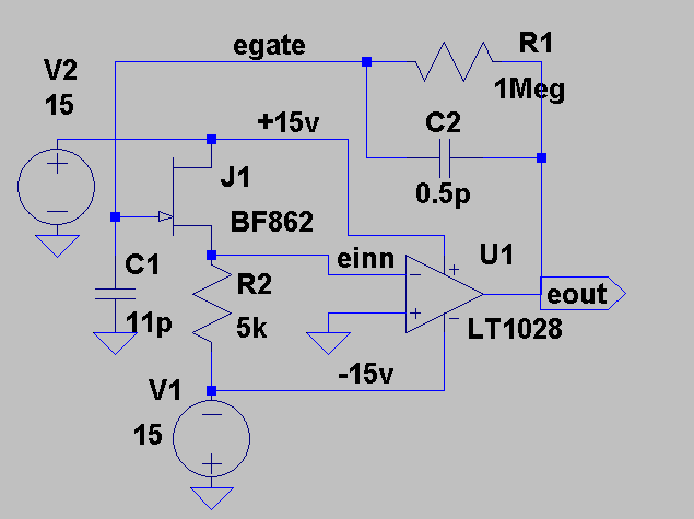
Now, in http://www.linear.com/product/LT1028, Linear Technology shows us how create an effective FET-input op amp from a discrete junction FET and a bipolar op amp.

The circuit is

Synthetic FET input op amp

The data sheet for the discrete N-channel junction FET BF862  is  http://www.nxp.com/documents/data_sheet/BF862.pdf

C1 represents the source impedance.  the circuit will work if the source impedance is partially (a resistor and capacitor in series or parallel) or totally resistive, also.

The JFET is used as a source follower to lower the effective source resistance seen by the bipolar op amp LT1028.  The total equivalent input noise voltage for this synthesized FET-input op amp is the quadrature sum of the two noise voltage sources, the JFET and the op amp:  sqrt (0.8e-9^2 + 0.85e-9^2) = 1.17 nanovolt/root Hz.

The discrete FET does add phase lag to the forward transfer function of the synthesized amplifier.  However, the FET has a transition frequency of 715 MHz., so phase lag at 50 MHz. will probably be under 0.1 radians (6 degrees).  The gain-bandwidth product of the LT1028 op amp is 50 MHz., so the closed loop gain even in a unity gain configuration will be under one, for frequencies above 50 MHz., and thus excess phase lag above 50 Mhz will not cause instability.

The BF862 is a particularly good JFET for this purpose, having low voltage noise and high bandwidth.  Other op amps could be used instead of the LT1028, where needed, but if they have a gain-bandwidth product above 50 MHz the synthesized amplifier may not be stable.

As always, this amplifier should be modeled in Spice (I suggest using LTSpice  IV http://www.linear.com/designtools/software/#Amp), using worst-case parameters.

Larry MIller